Good Installation Practice
Before Installation 
- Read and understand the Instruction Different model are different in installation manner
- Inspect the contents in the box. Defect contents could cause problem.
During Installation 
- Tighten bolt/nut between motor and pipe firmly. Failure will cause wear and tear effect due to jerking effect.
- Ensure Bolt/ nut (Rubber suspension) do not over tighten. Rubber suspension to absorbed vibration and jerking effect.
- Safety Wire are fixed as Installation Guide. Failure will caused C-Fan dropped.
- Do not mixed blade. Different blade will caused wobbling
- Fixed the motor complete with blade before fix to pipe. Bend Blade caused wobbling
- Ensure power terminal are fixed properly Prolong in proper installation will cause sparking.
- Ensure Canopy do not touch Keep no Noise and tear Effect on the ceiling
After Installation 
- Ensure all screw/nut are fully tighten. Ensure Safety
- Do not clean the blade by pulling blade tip Blade will bend if excessive force and resulted wobbling
- Fill up information stated in the guaranteed card and return the sale agent. To ensure that the user can be contacted if any matter arise
- Keep information regard seller, contractor After sales & Service
- Find out the after Sales and Service Centre To ensure better after service deal.
Installation Guide
Installation Of 1 Unit Ceiling Fan The main features of a ceiling fan is to move the entire air in the room, not creating a local wind as in other fans. To determine the model and mounting position, consider the condition below:H : distance form blade to floor (M) R : radius of effective floor space of wind spread (M) S : effective floor area (M2)
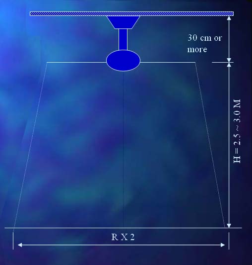
Calculation Formula R : coefficient x H S : hR2, where h = 3.14
| Size of Blade | H (M) | S (M2) | Coefficient |
| 120 cm | 2.5 | 8.3 | 0.65 |
| 120 cm | 3 | 12.5 | 0.66 |
Calculation If More Than One Unit Required
|
L |
Distance between ceiling Fan to another (pitch in M) |
| A | Distance of overlapping air throw between fan |
| B | Distance between tip of fan to wall |
| BL | Blade length (M) |
| L | (RX2) – 0.4, where 0.4 is maximum allowable overlapping of air throw between fan |
| L | (RX2) – 0, if minimum A = 0 |
| To calculate B = R – BL | |
Important Point For Safety And Performance
 Before Installation Do not use ordinary pipe to replace standard pipe supplied by the manufacturer. It may not withstand high load or torque created and can cause material failure eg. Conduit pipe
 Manual drilling of pipe hole can cause hole slanting. If it happens, fan will be wobble and in worse condition cause bolt worn out.
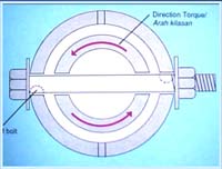 The bolt and nut for pipe and fan shaft must be tightened firmly. If its not, the bolt will easily worn out due to torque action during each starting action.
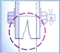 Do not modify the pipe (as shown below) because it can cause the material to break
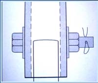 Do not use pipe with bigger inner diameter and not slot. This could lead to similar failure as 3. Do observe this installation condition that could lead to poor performance i) Beam within swipe distance. ii) Slanting Roof iii) High ceiling
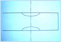
Stream Of Wind Movement
 Diagram 1 : The stream of wind movement is smooth and steady. The delivery and coverage area is maximum.Installation Condition : Ceiling Fan installation height > 30 cm.
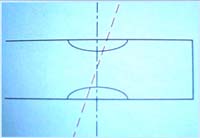
 Diagram 2 : Room size too small. The stream of wind movement not steady and air turbulence is created. This condition can cause the fan to wobble. (air noise may also be created). Recommendation : To install small size ceiling fan eg. 48″ type
Diagram 3 : The ceiling fan installation height < 30 cm (too close to the ceiling) The stream of wind is inferior and efficiency drops and noise may be created. Recommendation : To increase the ceiling fan pipe > 30 cm (minimum)
Causes Of Fan Wobbling And How To Improve
| Causes of Fan Wobbling | Action to Improve |
| Difference in blade weight | Ensure the weight stated on each blade is the same |
| Difference in height of blade tip | Change new blade or try re-adjusting the tip height with a measuring tool |
| Pipe length is less than standard | Use standard pipe. |
| Screw at shaft and pipe is loose | Fasten screw firmly |
| Screw at pipe between hook and absorber is too tight | Loosen the screw. |
| Pipe is modified with screw hole slanting | Ensure the hole is not slanting |
| Obstruction of beam in-between blades | Avoid the beam |
| Fan located at narrowing roof. | Avoid the roof |
| Motor not balanced. | Try using different blades. |
| Difference in blade angle | Change to a new blade |
Introduction
In our investigation and experience we found that many general problems of wall fan motor such as
- Shorter motor life
- Inconvenience for servicing
- Durability of part
were caused by the following factor:
- High motor temperature rise
- Big voltage fluctuation
- Type of bearing used improper
By gathering more information and feedback from consumers and further follow-up analysis it has proven that in areas when heavy duty performance is required (e.g. wall fan), we must use ball bearing motor.
Why Wall Fan Needs Ball Bearing
- Incline Position
 The wall fan is used at a different incline angle. During rotation of motor, oil flows out of the bearing by the way of the shaft.Shaft rings are located before the bearing and rotate simultaneously with the shaft.Oil which has flowed out is shaken away by centrifugal force and received back by the oil stopper to be absorbed in the felt ring, then moves again to the bearing.But if the incline angle is at minimum position (as shown) , oil will drip out instead of being collected back by the felt.
 - Atmosphere
 Wall fan is used normally at commercial and industrial places which are exposed to high temperature, humidity, dust and chemical atmosphere. In this condition, oil condensation is at maximum rate and unwanted particles are trapped in between the shaft and bearing.
Type of Bearing
- Circulation Lubrication
Bearing is lubricated by automatic oil circulation system during shaft rotation. The metal contained thousands of tiny air pockets which accumulated with oil. Felt ring acts as oil storage which then channel out oil to the metal.
- Ball Bearing
The bearing is lubricated by grease lubrication system. Grease is kept in sealing shield to prevent leak. Dust, moisture of foreign particles are prevented from entering the bearing. Ball bearing is expensive compared with the conventional type.
Advantages of Ball Bearing
- The bearing uses grease with higher dripping point (195 degree)
- Large operating range temperature ( -40 ~ 180 degree)
- Better sealing shield to prevent leaking of lubricant and avoid foreign particles entering the casing
- Easy bearing replacement
- Increase motor performance (less motor friction)
- Bearing is easy available in the market.
- Less precaution during assembly
- Cheaper cost for replacement
Technical Facts With Ball Bearing Motor
Figure 1 : Relationship of Temperature Rise against Time between motor using Ball Bearing and Metal Bearing
Figure 2 : Relationship of Temperature Rise against Voltage Fluctuation between motor using Ball Bearing and Metal Bearing
Figure 3 : Graph shown the starting voltage at notch 1 & 3 between Ball Bearing and Metal Bearing motor.
What is your selection?
- Wall Fan With Ball Bearing
- Equipped with Thermal fuse
- Lower Operating Temperature
- Long Establishment Manufacturer
Introduction
What is Ventilation ?
Is the means of circulating and distributing the air in a room or enclosed space.
There are 2 types of ventilation :
- Natural ventilation
Utilizes the pressure difference of outside air & circulation of air. - Mechanical ventilation
Uses air moving equipment (Fan) to generate pressure difference for air flow.
How ventilating fan can provide a healthier and comfort living
Installation Guide
Performance Criteria – Reliability Design
Metal Structure Design
- Metal Support
- Not easy deformed
- Safety and Security
- Metal Frame
- Strong
- Heat dispersion
- Metal Shutter
- Durable to rain and shine
Bearing Design
Conventional (Competitors’) Bearing Design
Suitable for Horizontal applications only but at your own risk if installed vertically
Why?
It may causes :
1. Oil dripping for vertical use
2. May cause hazard. eg. Fire

- Suitable for all applications
- Longer Lifespan
- Higher Performance Motor
Performance Criteria – Energy Efficiency
If TNB charge RM0.23/Kw of Electricity :
| National : Operation cost | |
| = RM0.23 x 24 / 1,000 x 24hrs x 30days | = RM 3.97 |
| Competitor : Operation cost | |
| = RM0.23 x 40 / 1,000 x 24hrs x 30days | = RM 6.62 |
| Cost Saving = RM6.62 – RM3.97 | = RM 2.65/month |
| Cost Saving Annually | = RM 31.80/year |
Performance Criteria – Energy Efficiency
If TNB charge RM0.23/Kw of Electricity :
| TYPE | MODEL | AIR VOLUME | |
| M3/MIN | M3/HR | ||
| WALL | FV-30LUM | 21.2 | 1,272 |
| FV-20AUM2 | 8.5 | 510 | |
| FV-25AUM2 | 13.8 | 828 | |
| FV-30AUM2 | 21.2 | 1,272 | |
| CEILING | FV-25TGU2 | 10.4 | 624 |
| INDUSTRIAL | FV-40AUM1 | 33 | 1,980 |
Performance Criteria – Safety
Built in thermal fuse
- No fire hazards
- Protect other component from damage
- Reduce repairing cost
Temperature in motor will increase due to:-
- Fluctuation of voltage
- Short circuit
- Motor jammed
- Overload
How To Calculate the Type & Number of Ventilating Fan required
Example 1
| STEP 1 : DETERMINE ROOM SIZE ( M3 )2.5 m x 8 m x 10 m =200 m3 —– (A) STEP 2 : DETERMINE THE NECESSARY FREQUENCY OF VENTILATION ——- (B)
STEP 3 : MULTIPLY (A) x (B) 200 x 6 = 1,200 M3/Hr STEP 4 : IDENTIFY SUITABLE MODEL FOR REFER TO AIR VOLUME SPECIFICATION IN CATALOG FV-30AUM2 AIR VOLUME = 1,272 M3/Hr … 1 unit |
Example 2
| STEP 1 : DETERMINE ROOM SIZE ( M3 )16 m x 10 m x 4 m =640 m3 —– (A)
STEP 2 : DETERMINE THE NECESSARY FREQUENCY
STEP 3 : MULTIPLY (A) x (B) 640 x 20 = 12,800 M3/Hr STEP 4 : IDENTIFY SUITABLE MODEL FOR REFER TO AIR VOLUME SPECIFICATION IN CATALOG FV-40AUM AIR VOLUME |